Childhood Adenotonsillectomy Trial
6.5.9 Electrode Placement Measurement
Proper sensor placement is very important for effectively recording sleep patterns and for consistency of data between sites. The PSG technician may prefer to measure and mark the head before beginning to apply the electrodes or during application. Head measurement is required; estimated placement of scalp electrodes is not acceptable.
The process for placing EEG sensors on the subject will follow the 10-20 system for electrode placement. This standard was developed to provide consistent application of EEG electrodes for the collection of brain waves. This system is based on measurements from 4 standard points (landmarks): the nasion, inion, and left and right pre-auricular points.
Identify your landmarks:
-
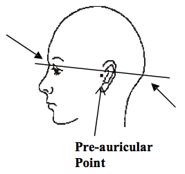
Pre-auricular points: Standing at the side of the subject, look at the ear. In front of the ear canal is a small flap of cartilage called the tragus. Just above the tragus is the point at which the top of ear lobe begins to form. The small dimple-like indentation between the tragus and the formation of the top of the ear lobe is the pre-auricular point. If in doubt, ask the subject to open and close his jaw. Look and feel for movement at the indentation above the tragus. Using blue china marker, lightly mark these landmarks on both the right and left sides of the participant.
- Nasion: Facing the subject, look into his/her eyes. Find the small dip at the bridge of the nose between the eyes. This point at which the forehead meets the nose is the nasion. Lightly mark the nasion.
-
Inion: Using a comb, unpadded cotton swab end or hair clip part the subject’s hair down the center, in the back of the head. Starting at the nape of the neck, run a finger up the back of the participant’s head until a bony ridge, or bump, can be felt. Having the subject move his/her head up and down may help you to identify this bony ridge. The slight hollow just beneath this bony ridge is the inion. Lightly mark the inion. This landmark may be difficult to feel on some individuals.
When the inion cannot be determined use the following method:
- Re-identify the nasion, which has been lightly marked.
- Re-identify both pre-auricular landmarks, which have been lightly marked.
- Standing on the side of the subject, visualize an imaginary line forming a band around the head using the nasion and pre-auricular sites that have been marked. The back of this imaginary band should identify the inion. Mark the inion lightly.
Measure for electrode sites:
- Distance measurements are done with a metric tape measure, and taken in centimeters (cm.) and millimeters (mm.). When computing percentages to find the electrode site a quick measurement guide can be found below, as well as in the Equipment Maintenance Section. The guide can be photocopied and kept with your prep materials for handy reference.
- All marks on skin must be done with a non-toxic, non-permanent implement, such as a wax-based china marker. Bright blue is most easily seen against dark hair. Red can be misidentified as blood by the subject or family members, therefore is discouraged.
- When working with subjects having long or thick hair, create a part in the hair by means of a comb or the unpadded end of a cotton-tipped swab; then hold the hair in place with hair clips while you work. The skin must be visible at the electrode sites because the electrode must rest on the skin, not on hair.
- All scalp electrode sites are determined by creating 2 lines that intersect. The electrode is placed over the point at which the 2 lines cross.
Quick Reference: Measurement Chart
| Total Measurement Value (cm.) | 50% Value (cm.) | 20% Value (cm.) |
|---|---|---|
| 25 | 12.5 | 5.0 |
| 26 | 13.0 | 5.2 |
| 27 | 13.5 | 5.4 |
| 28 | 14.0 | 5.6 |
| 29 | 14.5 | 5.8 |
| 30 | 15.0 | 6.0 |
| 31 | 15.5 | 6.2 |
| 32 | 16.0 | 6.4 |
| 33 | 16.5 | 6.6 |
| 34 | 17.0 | 6.8 |
| 35 | 17.5 | 7.0 |
| 36 | 18.0 | 7.2 |
| 37 | 18.5 | 7.4 |
| 38 | 19.0 | 7.6 |
| 39 | 19.5 | 7.8 |
| 40 | 20.0 | 8.0 |
Note: If the total value measurement contains a fraction, continue to use the percentage values as the whole number.
Example: Total measurement = 35.2, 35.5, 35.7 continue to use the percentage values for 35.
Remember: The 50% values are used to determine Cz. The 20% values are used to determine C3 and C4.
To determine Cz:
1) Have the subject sit in a chair. Standing at the side of the subject, place the zero line (0) of the tape measure on the marked inion. Holding the tape measure in place with your non-dominant hand, stretch the tape measure upwards, over the crown of the head, until it reaches the marked nasion. Determine the total distance between the inion to nasion, in centimeters. Remember this number (it may help to write it down). Compute 50% of this total measurement (or use your measurement guide).
2) Remove the tape measure, and re-position with the zero line on the marked nasion. Stretching the tape measure upwards, over the crown of the head, mark the value for 50% of the nasion to inion total. When marking these sites, make a large enough line so it can be easily found.
3) Remove the tape measure and stand behind the subject. Place the zero line of the tape measure on the left pre-auricular mark. Stretch the tape measure over the top of the head, and along the mark that has just been made, until it reaches the right pre-auricular mark. Determine the total distance from pre-auricular to pre- auricular in centimeters. Remember this number (it may help to write it down). Compute 50% of this total measurement (or use your measurement guide). While firmly holding the tape measure at the left preauricular mark allow the tape measure to drape over the crown of the head while marking the value for 50% of the total measurement. This mark should intersect the previously made line. The point at which the lines intersect is the site for the Cz electrode placement.
To determine placement of REF at FPz:
4) Looking at the participant’s face locate the nasion and place the zero line of the tape measure on the nasion. Using the total distance measured from inion to nasion (step 1) compute 10% of this total measurement. Mark the 10% value from the tape measure as a straight horizontal line across the participant’s forehead. Remove the tape measure and extend this line on each side to above the middle of the eyebrow, taking care to not raise or drop the ends from the 10% location. Looking straight at the participant’s face make a dot in the middle of the eyebrows then extend this dot into a vertical line that intersects the previously marked horizontal line. The point at which the lines intersect should be the middle of the forehead and in straight line with the mark for Cz. This location is known as FPz. Place the REF electrode here.
5) Measure the circumference of the participant’s head. Remember this number (it may help to write it down). Compute 5% of this total measurement. Place the zero line on the mark for FPz and mark a vertical line at the 5% measurements to the left (FP1) and right (FP2) of FPz. Double check your marks by measuring the distance between FP1 and FP2. The distance between these 2 locations should equal 10% of the total circumference measurement.
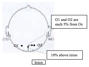
To determine O1 and O2:
6) Stand behind the subject, part the hair down the middle of the head (from Cz downward) and locate the inion. Compute 10% of the value of the inion-nasion total (step 1). Place the zero line of the tape measure on the inion, measure a total of 10% cm up from the inion and make a horizontal mark across the back of the head. Extend this line this line on each side taking care to not raise or drop the ends from the 10% location.
7) Place the zero line of the tape measure on FPz and measure 50% of the total circumference (step 5) making a vertical line at the 50% location. This line should intersect the horizontal line 10% above the inion. This intersection mark is Oz. Compute 5% of the circumference total. Place the zero line of the tape measure on the mark for Oz and mark a vertical line at the 5% measurements to the left (O1) and right (O2) of Oz. Double check your marks by measuring the distance between O1 and O2. The distance between these 2 locations should equal 10% of the total circumference measurement. Stand back from the participant and visually check that these marks are in the middle of the back of the head and not shifted to the left or right (indicating that the Oz measurement was incorrect).
To determine C4:
8) Stand on the right of the participant. Place the zero line of the tape measure on Cz. Remembering the total distance from pre-auricular to pre-auricular (step 3) compute 20% of the total measurement. Stretching the tape downwards toward the ear make a horizontal line across the side of the participants head at the 20% value. Part the hair and hold it in place with a comb if necessary in order to properly visualize your mark.
9) Next place the zero line of the tape measure on the O2 mark. Stretch the tape forward to the mark for FP2, making sure that the edge of the tape runs along the horizontal line you have just made on the side of the head. Measure the total distance between O2 and FP2, compute 50% of the total and make a vertical line to intersect with the horizontal. This is the site for the C4 placement.
To determine C3:
- 10) Standing on the left of the participant repeat the steps for determining C4, marking the 20% horizontal line from Cz and using the distance between FP1 and O1 to compute the 50% vertical line. This location on the left side of the head is C3.
To determine F4:
- 11) Lay the tape measure between the mark for FP2 (above the right eyebrow) and C4. Measure the distance and make a horizontal mark at 50% of the total distance. This mark should be in line with FP2 and C4. This location on the anterior right of the head is F4.
To determine F3:
- 12) Lay the tape measure between the mark for FP1 (above the left eyebrow) and C3. Measure the distance and make a horizontal mark at 50% of the total distance. This mark should be in line with FP1 and C3. This location on the anterior right of the head is F3.
To determine T4:
13) Stand on the right of the participant. Place the zero line of the tape measure on the pre-auricular point. Remembering the total distance from pre-auricular to pre-auricular (step 3) compute 10% of the total measurement. Stretching the tape upwards toward C4 make a horizontal line across the side of the participants head at the 10% value.
14) Now remembering the total head circumference value (step 5) compute 20%. Place the zero line of the tape on FP2, run the tape circumferentially along the participants head making sure that the edge of the tape runs along the horizontal 10% line. Make a vertical line to intersect at the 20% value. This location is T4. Stand back to visualize the marked locations, T4 should be roughly above the tragus of the ear and C4 in line with T4 and Cz.
To determine T3:
- 15) Standing on the left of the participant repeat the steps for determining T4, marking the 10% horizontal line upwards from the left pre-auricular and using 20% of the total circumference from FP1 to compute the vertical line. This location on the left side of the head is C3. Stand back to visualize the marked locations, T3 should be roughly above the tragus of the ear and C3 in line with T3 and Cz.
To determine M1 and M2:
These placement sites are on the mastoid process (bone behind the earlobe). The electrode should be placed on the skin between the crease of the earlobe and where the hairline begins. Lightly mark these sites. M1 is placed on the left mastoid, M2 on the right.
To determine EOG placements:
The EOG recording electrodes are placed about 1 cm. (one finger breadth) lateral to and 1 cm. below the outer canthus of each eye, (on the ridge of the orbital bone). Lightly mark these sites, and then stand in front of the participant to make certain that they correct. These EOG placements are in line, not staggered.

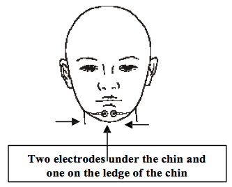
To determine chin EMG placement:
- The EEG waveforms in REM sleep resemble the waveforms of wakefulness. The facial muscles however, relax in REM sleep; therefore these EMG electrodes are crucial in correctly identifying REM sleep. These electrodes must be attached firmly to prevent displacement and to yield quality data through the recording period.
The two EMG electrodes are placed on each side of the geniohyoid muscle, which is a large muscle located underneath the chin. Having the subject activate this muscle may be helpful for determining the placement of the EMG electrodes. To activate the muscle, place your hand under the subject’s chin, between the tip if the chin and the neck. Ask the subject to swallow. You will feel the geniohyoid muscle move. The electrodes are placed on each side of this muscle but at least 3 cm. apart from each other. A redundant electrode is placed on the ledge of the chin (below the lower lip) as a back-up.
Reference:
A Review of the International Ten-Twenty System of Electrode Placement, 1974, The Grass Instrument Co., Quincy, Mass.
Electrode Site Preparation:
Electrodes must be placed in the correct locations to yield valid data.
Electrode sites must be properly prepared prior to electrode placement to insure tight bonding and low impedance values.
Secure attachment of gold disk electrodes is crucial to successful recording of data.
Before the attachment of gold disk electrodes the skin at the marked sites must be properly cleansed and lightly abraded. This insures low impedance values. Excessive impedance defeats the passage of signals into the electrode and, in turn, to the recorder. For optimal recording the impedance readings of the electrodes should be < 5 kΩ and should be balanced (values should be approximately the same). Exceptions are ECG and leg EMG, which can tolerate impedance values up to 30 kΩ.The use of alcohol on skin increases impedance. Alcohol should not be used in any phase of participant preparation.
Successful skin preparation prior to electrode placement helps to reduce the level of impedance thereby improving the quality of signal.
Skin preparation requires abrasion to the top layer of the subject’s skin at the electrode site. Although blood is not evident, the technician must understand that these areas are now non-intact skin and pose a risk for blood borne pathogens. Personal protective equipment (PPE) must be worn at all times when working with non-intact skin and equipment which has been in direct contact with non-intact skin (i.e.: used electrodes).
Use an abrasive preparation. Preparations such as Nu-Prep and Skin Pure contain relatively less pumice and may be preferred for those with sensitive or fragile skin while Lemon Prep has the highest volume of abrasive and is suitable for weathered scalp or if low impedance cannot be otherwise obtained.
Abrade only the area at the marked site. Gold disk electrodes have a diameter of 1 centimeter, therefore the abrasion should be limited to an area the size of or just slightly larger than the electrode. On marked sites, remember that the electrode should be placed where the 2 lines intersect.
The participant should know what to expect! Please communicate. You may choose to use the following script: “Before I attach the electrodes, I have to get your skin ready. I will be using a special cleaner that sets the skin up for a good contact. You may feel a little bit of scratching on your skin but it should not hurt, and it will not harm your skin.”
Preparing the Electrode Site:
1) Place a small amount of skin prep abrasive onto a clean disposable surface (i.e.: 4x4 gauze square or small plastic med. cup).
2) If working in a hairy area, separate the hair in order to see the skin. You may find a comb or hairclips useful to create a part and hold the hair back.
3) Use a cotton- tipped applicator to transfer a small amount of skin prep directly onto the electrode site. Before lifting the applicator, apply a moderate pressure and make small circular motions repeatedly on the skin. Take care that you include the center of the site, not just make circles around it leaving the center un-prepped. You may prefer to use a combination of back and forth strokes along with some circular motions.
4) Continuing with moderate pressure, slowly count to 5 while you scrub the site (1 one-thousand, 2 one-thousand, 3 one-thousand, 4 one-thousand, 5 one-thousand). You are done when the skin “pinks up”. Expect some subjects to have more fragile skin than others; keep an eye on what you do. You may have to adjust the pressure or the count time.
5) Prep abrasives are not designed as conductors; remove any excessive prep abrasive from the skin prior to electrode placement.
6) Repeat the above steps for each electrode site. It is much easier to prep 2 or 3 sites, and then to apply those electrodes, provided you do not lose your prepped sites.
7) Discard the applicator and prep abrasive when finished. Never contaminate your original tube or bottle.