Sleep Heart Health Study
Technical Notes on SHHS1
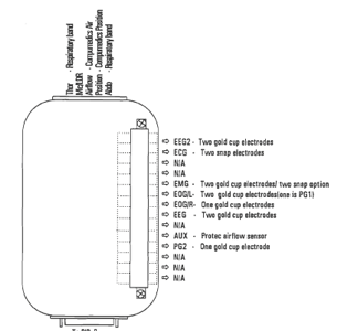
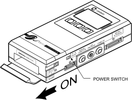
The Compumedics P-Series Sleep Monitoring System used for SHHS1 consisted of a Main Unit and Patient Interface Box (PIB). The signals were obtained by the use of electrodes/sensors that connected to the PIB via Harwin connectors. The PIB connected to the Main Unit using an analogue cable and signals were recorded in digitized format onto a solid-state memory device (PCMCIA Memory Card) in the Main Unit. The montage was set up so that only 2.01 Mb/hr of data was recorded, providing 10 hours of data for the 20 Mb flashcards which were used. The PIB had 6 switch banks with toggle switches which would control the amplifiers (on/off). The main unit was powered by a rechargeable Nickel Metal Hydride battery. The PIB and loose electrode wires and sensor cables were supported by a cloth “bib/vest” with the recording unit placed in the center pocket. This bib/vest was placed over the participants nightclothes. After collection the study would be downloaded to a computer via serial lead, battery recharged and flash card reformatted.
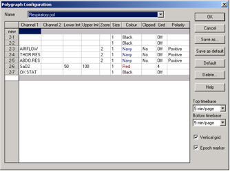
Collection Montage Sampling Rates
| Channel | Label | Sampling Rate | Sensitivity |
|---|---|---|---|
| 1 | SaO2 | 1 | |
| 2 | H.R. | 1 | |
| 3 | EEG2 | 125 | 250 uV |
| 4 | ECG | 125 | 2.5 mV |
| 5 | LEG/L | - | 2.5 mV |
| 6 | LEG/R | - | 2.5 mV |
| 7 | EMG | 125 | 62.5 uV |
| 8 | EOG/L | 50 | 250 uV |
| 9 | EOG/R | 50 | 250 uV |
| 10 | EEG | 125 | 250 uV |
| 11 | SOUND | 10 (optional) | x1 |
| 12 | AIRFLOW/OLD | 10 | x1 |
| 13 | THOR | 10 | x1 |
| 14 | ABDO | 10 | x1 |
| 15 | POSITION | 1 | |
| 16 | LIGHT | 1 | |
| 17 | AUX/AlRFLOW/ NEW | 10 | 250 uV |
| 18 | CPAP | - | |
| 19 | OX STATUS | 1 |
The Compumedics P-series Sleep Monitoring systems used for SHHS1 were prototype units that were refined and modified by Compumedics during study collection and there were proprietary function algorithms that were not always shared by the company engineers. For example, a different “weight” was given to the 2 EEG signals: EEG1 (C4-A1) visually appeared to be a “cleaner” signal (less high frequency within the waveforms) than EEG2 (C3-A2) however Compumedics would not share why.
In 2013 at request of the Reading Center, a Compumedics engineer ran simulations of the P Series schematic X5240A from Nov 98 to get the following freq. response:
Ch1        EEG/2  High pass filter -3dB 0.39Hz (2 pole),  Low pass filter -3dB 10.6 Hz (multiple poles)
Ch2        ECG    High pass filter -3dB 0.41Hz (2 pole),  Low pass filter -3dB  9.4 Hz (multiple poles)
Ch6/7      EOG    High pass filter -3dB 0.41Hz (2 pole),  Low pass filter -3dB  9.4 Hz (multiple poles)
Ch8        EEG    High pass filter -3dB 0.33Hz (1 pole),  Low pass filter -3dB  8.9 Hz (multiple poles)
Ch17 to 24 EEG    High pass filter -3dB 0.50Hz (1 pole),  Low pass filter -3dB 30.5 Hz (3 poles)
The P-series was not a truly digital system, the EEG inputs were hardwired into the amplifier interface and called EEG (C4-A1) and EEG2 (C3-A2) instead of all being collected to a common reference. These signals were collected without additional filtering but the high-pass hardware filters for the instrument were 0.15 Hz for EEG, EOG, EMG and ECG channels and 0.05 Hz for all respiratory signals. There was no ability to set a high filter (low band pass) at acquisition; signal collection began at the mechanical low filter start-up (0.15 or 0.05) and continued to collect without a frequency cut-off. For display a high filter was engaged using ½ of the sampling rate (Nyquist). For SHHS1 the sampling rate for EEG, EMG and ECG was set to 125 Hz, EOGs were sampled at 50, Respiratory signals were sampled at 10, Position, light and oximetry were sampled at 1Hz.
Amplification was set in the recording unit to be 2.5mV for ECG and leg channels, 62.5 uV for Chin EMG and 250uV for EEG, EOG. Snore MIC, airflow and respiratory signals were at a scale of 1.
The Recorder contained an built-in operating software called BIOS (short for Basic Input Output System) which contained instructions to perform recorder functions. The algorithm for A/D conversion was proprietary but there did appear to be a self-test at power-up with a display that would read:
A/D1...Ok
A/D2...Ok
Real time Clock...Ok
Sensors
EEG. Ground 1 (driven ground) placed on Cz. C4 (right central EEG) and C3 (left central EEG) placed on either side of CZ. A1 (left) and A2 (right) placed over bony prominences just behind each ear. C4 lead paired with A1 (EEG1), and C3 lead paired to A2 (EEG2). Grass brand gold disk surface electrodes used.
EOG. Ground1 (eye reference) placed on center of forehead, above the bridge of the nose (nasion). Right EOG placed so electrode center is one cm out and one cm down from the outer corner (canthus) of the right eye, on the bony ridge. Left EOG placed so the electrode center is one cm out and one cm down form the outer corner of the left eye, on the bony ridge. Grass brand gold disk surface electrodes used.
Thermistry/Thermocouple: The original Compumedics triple thermister a Y shaped chassis with nasal and oral bead sensors, used for the first few months of the study connected to the side of the PIB using a lemo connector and used Channel 12 named “Airflow” on the collection montage. The Compumedics thermister was uncomfortable and replaced with ProTech thermister M325. This thermister used the "auxiliary" channel as designated on the PIB (Channel 17). Sites were asked to modify the montage and name Channel 17 “New Air” so scorers would be able to tell when Compumedic thermister was used versus the Protech thermister. Instructions were sent to the sites on how to modify the collection montage (add channel 17). It took several attempts for some sites to correctly name this channel and modify the montage. As a result, some studies have this channel 17 named: “NEW AIR”, “NEWAIR”, “AIRFLOW”, “airflow”, "new A/F", "New Air" and/or “AUX.”
Chin EMG electrodes (2) placed on lower chin, separated by about 1-2 cm. Alternative site (if bearded): on chin surface, half way down from the lips, in area supported by boney ledge, or over masseter muscle.
ECG Placement: Medtronic Medclear ECG snap electrodes. 2 leads place R subclavicle-L lower rib. Occasional modesty issues necessitated altering placement to right subclavicle-left suubclavicle. Position 3-5 cm below the middle of the right and left collar bones, in spaces between rib bones.
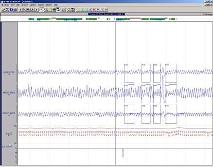
Respiratory Bands: White Respitrace Inductance Plethysmography. There was no SUM signal generation. When Respitrace no longer produced the belts, Compumedics refurbished the original bands and continued to provide repair service when needed.
Position Sensor: A mercury gauge, sensitive to changes in position, was embedded in the headbox. No special attachment was needed. Calibrated in the home. When viewing EDFs, the values for position are as follows: 0 (Right); 1 (Left); 2 (Back - Supine); 3 (Front - Prone).
Light sensor: There was a Compumedics light sensor interfaced to the PIB. The hook-up tech would calibrate this sensor in the home to ambient room light and darkness to collect a signal for lights off. This was not always reliable.
Oximetry: Nonin XPOD Model 3011, proprietary attachment to recording unit. Finger sensor 8000J. Some sites employed reusable sensors with flexi-fit sensor covers, some sites (Tucson) used disposable finger sensors. Both sensors had identical circuitry boards. In December of 1995 determined that there was a problem with circuitry board and Nonin sensors being used. All units were modified in January of 1996 to correct the problem with oximetry signals.
No leg EMG sensors were used. No Nasal Pressure sensor was used.
Sound not used due to questionable collection in the home picking up sound/snoring from bed partner.
